
OBD stands for On-Board Diagnostics, and it is a system that allows car garages and car owners to diagnose and troubleshoot problems in their vehicles. OBD works by communicating with the vehicle’s computer system, also known as the Engine Control Module (ECM) or Powertrain Control Module (PCM), and retrieving data about the vehicle’s performance, emissions, and other systems. In this article, we will discuss how OBD works, including the differences between OBD-I and OBD-II, how OBD communicates with a vehicle’s computer, OBD-II connector types and pinouts, and OBD-II protocol and communication standards.
Table of Contents
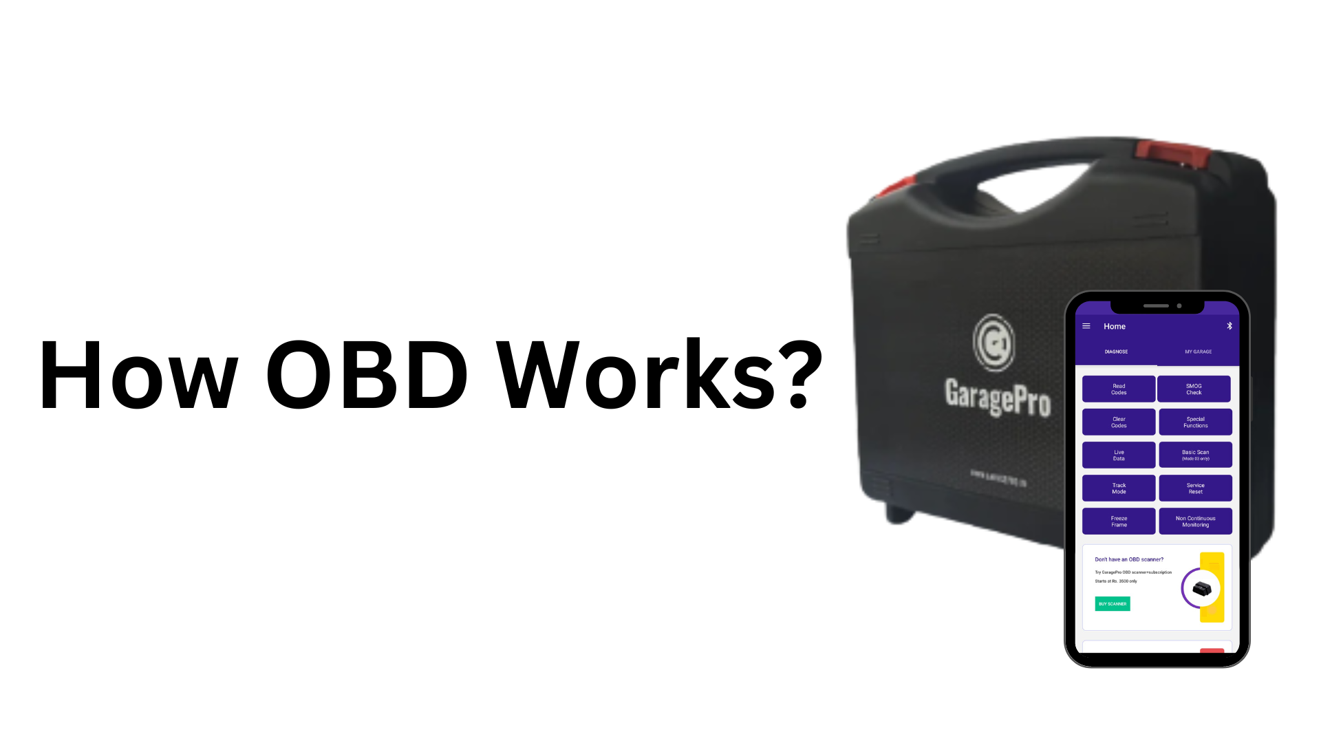
How OBD Works?
OBD-I vs. OBD-II
On-Board Diagnostics (OBD) systems have been around since the early 1980s. However, the systems have evolved significantly over time, resulting in two different generations of OBD systems – OBD-I and OBD-II. These systems are essential for ensuring that a vehicle operates within acceptable emissions levels, detects faults, and notifies the driver of any issues.
OBD-I was introduced in the early 1980s and was used on vehicles until the mid-1990s. It was a basic diagnostic system that could monitor a few basic components of the engine, such as the throttle position sensor and the oxygen sensor. It used a simple blinking light on the dashboard to indicate a fault code and required a specialized diagnostic tool to retrieve and interpret the codes.
OBD-II, on the other hand, is a more advanced diagnostic system that was introduced in the mid-1990s and is used on vehicles to this day. It is a standardized system that allows for more comprehensive diagnostic capabilities and includes a wider range of sensors. It uses a standardized diagnostic connector and can provide real-time data, as well as fault codes, to aid in the diagnosis of problems. It also includes a set of emissions-related diagnostic monitors that are continuously monitored, allowing for the detection of problems before they become more serious.
Understanding the differences between OBD-I and OBD-II is essential for diagnosing and repairing issues with a vehicle’s engine. Here, we will explore the details of these two systems and how OBD works in general.
OBD-I
OBD-I, or On-Board Diagnostics I, was the first generation of automotive diagnostic systems used by car manufacturers in the 1980s and early 1990s. It is a precursor to OBD-II, which is the current industry standard.
How OBD-I Works:
OBD-I systems function by collecting data from various sensors in the vehicle and transmitting that data to the vehicle’s Engine Control Module (ECM). The ECM then interprets the data and makes adjustments to the engine’s performance as necessary.
Key features of OBD-I
- Limited diagnostic capabilities: Unlike OBD-II systems, which are capable of detecting and reporting a wide range of engine and emissions problems, OBD-I systems have limited diagnostic capabilities. They are primarily designed to detect faults related to the vehicle’s emissions control system.
- Manufacturer-specific: Each car manufacturer had its own OBD-I system, which meant that the diagnostic codes and procedures used to access them could vary significantly from one brand to another.
- The difficulty of use: Diagnosing problems with OBD-I systems could be difficult for home mechanics due to the manufacturer-specific diagnostic codes and the need for specialized diagnostic equipment.
- Not standardized: Because OBD-I was not standardized, it was difficult for independent repair shops to work on vehicles from multiple manufacturers.
- Limited Data Retrieval: Unlike OBD-II systems, OBD-I systems are not capable of retrieving real-time data from the vehicle, making it harder to diagnose the problem and monitor the performance of the engine.
Pros and cons of OBD-I
Pros:
- OBD-I was a significant improvement over previous non-standardized diagnostic systems, providing technicians with more information about the vehicle’s performance and emissions.
- OBD-I diagnostic codes were relatively simple and straightforward, making it easier for mechanics to diagnose and fix problems.
- OBD-I systems were effective in identifying problems related to emissions, which helped to reduce pollution and improve air quality.
- OBD-I systems were capable of providing valuable diagnostic information on a range of vehicle systems, including the engine, transmission, and brakes.
Cons:
- OBD-I systems were not standardized across different vehicle manufacturers, which meant that each manufacturer had its own unique set of diagnostic codes and procedures.
- OBD-I systems had limited diagnostic capabilities compared to later versions, such as OBD-II.
- OBD-I systems were not capable of providing real-time data, which meant that mechanics had to rely on static diagnostic codes to diagnose problems.
- Due to the lack of standardization and limited capabilities, OBD-I systems were less user-friendly than later versions and required specialized knowledge and equipment to diagnose and repair problems.
Overall, while OBD-I was a significant improvement over earlier diagnostic systems, it was not as advanced or user-friendly as later versions such as OBD-II. However, it laid the groundwork for the development of more advanced diagnostic systems and paved the way for more effective emissions control measures.
OBD-II
OBD-II, also known as On-Board Diagnostics II, is the second generation of on-board diagnostics systems used in vehicles. This system was introduced in the mid-1990s, replacing the earlier OBD-I system. OBD-II has become the industry standard in modern vehicles, providing more advanced diagnostics and improving vehicle emissions control.
Here is a breakdown of OBD-II and how it works:
What is OBD-II?
OBD-II is a diagnostic system that monitors a vehicle’s performance and emissions, identifying problems that affect performance and fuel efficiency. It uses a standardized system of diagnostic trouble codes (DTCs) to communicate with a scan tool or code reader, providing a detailed report of the vehicle’s condition.
How does OBD work? (OBD-II)
The OBD-II system continuously monitors a vehicle’s performance and emissions, collecting data from various sensors throughout the vehicle. The system compares the data collected to predetermined values and thresholds, triggering a DTC if the data falls outside these limits. These codes can then be read and interpreted by a scan tool or code reader, allowing technicians to identify and diagnose the issue.
OBD-II Components
The OBD-II system consists of several components, including:
- Engine Control Module (ECM): The ECM is responsible for monitoring the vehicle’s performance and controlling the engine’s functions.
- Sensors: Sensors throughout the vehicle monitor various components, such as the oxygen sensor, mass airflow sensor, and more, sending data to the ECM.
- Actuators: Actuators are components that are controlled by the ECM, such as the fuel injectors and the idle control valve.
Benefits of OBD-II
OBD-II provides several benefits, including:
- More accurate and detailed diagnostic information.
- Standardized DTCs and scan tool communication, making it easier for technicians to diagnose issues.
- Improved emissions control, helping to reduce pollution and protect the environment.
- Real-time data on vehicle performance, potentially improving fuel efficiency.
Drawbacks of OBD-II
Despite its benefits, OBD-II also has some drawbacks, including:
- Limited compatibility with older vehicles, as OBD-II was not mandatory until 1996.
- Limited access to advanced diagnostic information, as some manufacturers restrict access to proprietary data.
- Potentially costly repairs, as the advanced diagnostic information provided by OBD-II can make repairs more complex and time-consuming.
In conclusion, OBD-II is a more advanced and sophisticated system than its predecessor OBD-I, providing more accurate and detailed diagnostic information. While it has some drawbacks, it has become an industry standard for modern vehicles and has greatly improved emissions control and vehicle performance.
How OBD communicates with a vehicle’s computer
OBD communicates with a vehicle’s computer (ECM) using a variety of protocols, depending on the version of OBD and the make and model of the vehicle. OBD-I used a variety of proprietary communication protocols, while OBD-II uses a standardized protocol called Controller Area Network (CAN). CAN is a serial communication protocol that allows devices to communicate with each other over a single wire.
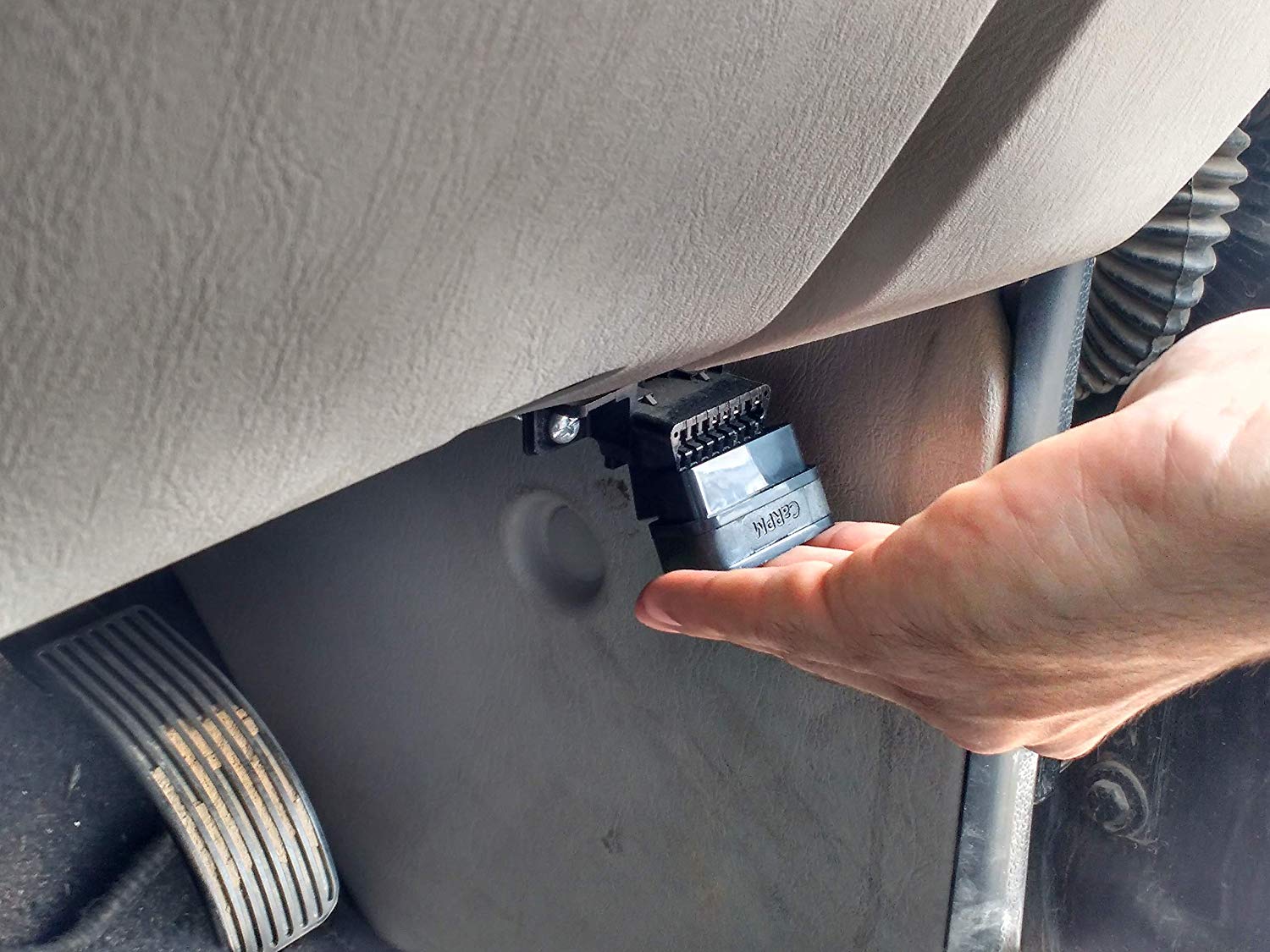
When a diagnostic scan tool is connected to a vehicle’s OBD-II port, it sends a request to the vehicle’s computer for data. The computer then responds with a stream of data, which includes information about the vehicle’s performance, emissions, and other systems. The scan tool can then interpret this data and display it to the user in a readable format.
OBD-II connector types and pinouts
OBD-II (On-Board Diagnostics) is a standardized system that was introduced in the mid-1990s to help diagnose issues in vehicles. OBD-II systems are mandatory on all new vehicles sold in the United States and Europe, and it has become the industry standard worldwide. The OBD-II system has a diagnostic connector that is used to connect with the vehicle’s onboard computer, and this connector comes in different types and pinouts. Here, we will discuss the various OBD-II connector types and pinouts.
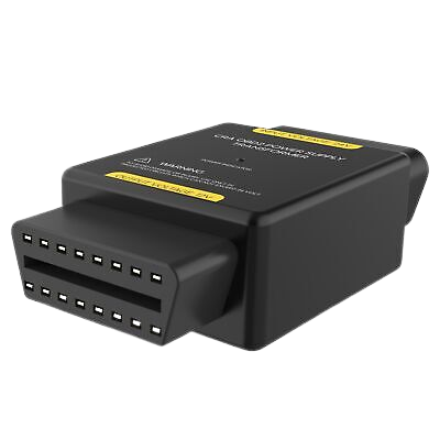
OBD-II Connector Types
The OBD-II connector types are categorized into three types: Type A, Type B, and Type C.
- Type A: This connector is also known as the J1962 connector. It has 16 pins and is used in most vehicles. Type A connectors are further divided into two sub-types: A1 and A2.
- Type B: This connector has 20 pins and is used in some heavy-duty trucks and buses. It is not commonly found in consumer vehicles.
- Type C: This connector has 14 pins and is used in some Asian and European vehicles. It is also not commonly found in consumer vehicles.
OBD-II Pinouts
The OBD-II pinouts are different for each connector type. The following are the pinouts for each connector type:
- Type A1: Pin 2 (J1850 Bus+), Pin 4 (Chassis Ground), Pin 5 (Signal Ground), Pin 6 (CAN High), Pin 7 (K Line), Pin 10 (J1850 Bus-), Pin 14 (CAN Low).
- Type A2: Pin 1 (Manufacturer’s discretion), Pin 3 (Manufacturer’s discretion), Pin 8 (Manufacturer’s discretion), Pin 9 (Manufacturer’s discretion), Pin 11 (Manufacturer’s discretion), Pin 12 (Manufacturer’s discretion), Pin 13 (Manufacturer’s discretion), Pin 16 (Battery Power).
- Type B: Pin 1 (Manufacturer’s discretion), Pin 2 (J1850 Bus+), Pin 4 (Chassis Ground), Pin 5 (Signal Ground), Pin 6 (CAN High), Pin 7 (ISO 9141-2 K Line), Pin 10 (J1850 Bus-), Pin 14 (CAN Low), Pin 15 (Manufacturer’s discretion).
- Type C: Pin 1 (Manufacturer’s discretion), Pin 4 (Chassis Ground), Pin 5 (Signal Ground), Pin 7 (K Line), Pin 9 (Manufacturer’s discretion), Pin 10 (J1850 Bus-), Pin 11 (Manufacturer’s discretion), Pin 12 (Manufacturer’s discretion).
In conclusion, OBD-II connector types and pinouts are essential to diagnose and maintain vehicles effectively. By understanding the connector types and pinouts, mechanics and vehicle owners can better diagnose and fix issues with their vehicles. However, it is essential to note that the pinouts and connector types can vary depending on the vehicle make and model. Therefore, it is crucial to consult the vehicle’s manual or a professional mechanic for accurate information.
OBD-II protocol and communication standards
OBD-II (On-Board Diagnostics II) is a standardized system used in modern vehicles to monitor and diagnose engine and emissions-related issues. The system communicates with various sensors and modules in the vehicle, providing important diagnostic information to technicians and DIY mechanics. OBD-II protocol and communication standards define how this information is transmitted between the vehicle’s onboard computer and diagnostic tools.
OBD-II Protocol:
- The OBD-II protocol specifies the rules and guidelines for how data is communicated between the vehicle’s onboard computer and diagnostic tools. There are five main protocols that are used in OBD-II systems: SAE J1850 PWM, SAE J1850 VPW, ISO 9141-2, ISO 14230-4 (KWP2000), and ISO 15765-4 (CAN-BUS).
- Each protocol has its own specific communication protocol and data rates, and not all protocols are supported by every vehicle make and model.
- CAN-BUS is the most commonly used protocol in modern vehicles and offers the highest data rates and reliability.
Communication Standards:
- The OBD-II system uses standardized communication standards to ensure that diagnostic tools and software are able to communicate effectively with the vehicle’s onboard computer.
- The OBD-II communication standards define the type of information that is transmitted, the format in which it is transmitted, and the protocols used to ensure data integrity and reliability.
- The most commonly used communication standard is the OBD-II PID (Parameter ID) standard, which defines a set of standard diagnostic parameters that can be accessed and monitored by diagnostic tools.
OBD-II Communication Process:
- The OBD-II communication process involves a series of steps that enable the diagnostic tool to access and retrieve diagnostic information from the vehicle’s onboard computer.
- First, the diagnostic tool establishes communication with the vehicle’s onboard computer using the appropriate protocol and communication standard.
- Next, the diagnostic tool sends a request for specific diagnostic information using the OBD-II PID standard.
- The vehicle’s onboard computer then sends the requested diagnostic information back to the diagnostic tool, which can then be analyzed and interpreted by the technician or DIY mechanic.
In conclusion, understanding OBD-II protocol and communication standards is essential for effective diagnostic and repair work on modern vehicles. Different protocols may be used in different vehicle makes and models, and it’s important to ensure that diagnostic tools are compatible with the specific protocol used by the vehicle. Furthermore, the use of standardized communication standards ensures that diagnostic tools and software are able to effectively communicate with the vehicle’s onboard computer and retrieve accurate diagnostic information.
OBD-II uses a standardized protocol called Controller Area Network (CAN) and a universal 16-pin connector. The OBD-II protocol supports a variety of communication standards, including ISO 9141-2, J1850 PWM, J1850 VPW, and ISO 14230-4 (KWP2000). By standardizing the diagnostic process, OBD-II has made it easier and more affordable for car owners and mechanics to diagnose and repair problems in vehicles. So this is how OBD works, If you have any doubts or question please feel free to comment below.